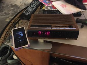
The Panasonic RC-6064 is an AM/FM clock-radio produced in the late 80s and early 90s. This one I received as a Christmas gift in 1989 and has served me well over the past 28 years. A few years ago I tried to replace it with a newer clock-radio that had an iPod dock. The blue lights from the new clock-radio keep me up at night, so it was time to switch back. Two things my childhood clock-radio always needed was aux-in and an external FM antenna. Thanks to the chipset diagrams available online I was able to figure where I could mod the circuit to add these.
Aux-In
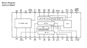
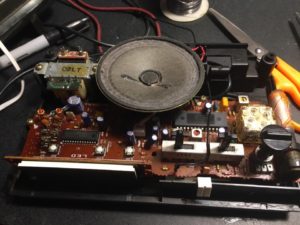
The clock-radio uses a Sony CXA1019P IC (IC2 on the board), an AM/FM IC with built in power amp. By tapping into the AF in pin (pin 24) for the power amplifier, I was able to wire a 3.5 mm (1/8th) headphone jack directly in.
External Antenna
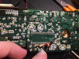
The external antenna took a little bit more work to figure out. I had to figure out where in the circuit I could tap an antenna into. Using circuit diagrams I found in a google search I was able to discern that the antenna circuit should come off of the FM RF in pin (pin 12). From there I used a test lead on a weak station to identify the ideal spot on the circuit board to solder the antenna lead to. I ended up following the traces and found an unused hole immediately in front of the radio/alarm on/off switch. I was able to wire the lead to there and ran it out through the back of the case.
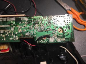
The wire is soldered to the antenna circuit which happens to have a trace running along the top of the board in this photo
Final Results
It is all working. The aux-in works great with my various audio players and cell phones, the external FM antenna helps me to better pull in the public radio station I enjoy listening to.
